> Clearly this was an enormously time-wasting proceeding that must have added greatly to the expense of all general machining operations. Joseph Whitworth's patent provided for the dividing of the nut axially and the mounting of each half in a slideway forming part of the lathe saddle itself, the opening and closing of the nut being controlled by a lever mounted on the front of the saddle apron. At the same a pinion or a train of gears, mounted behind the apron and engaging a rack fastened to the front of the lathe, allowed the operative to wind the saddle back quickly as soon as the clasp nut was opened. In this way the time lost between cuts along the work was reduced to a fraction of what it had been previously. The clasp nut and its disposition are illustrated in Fig. 1.14
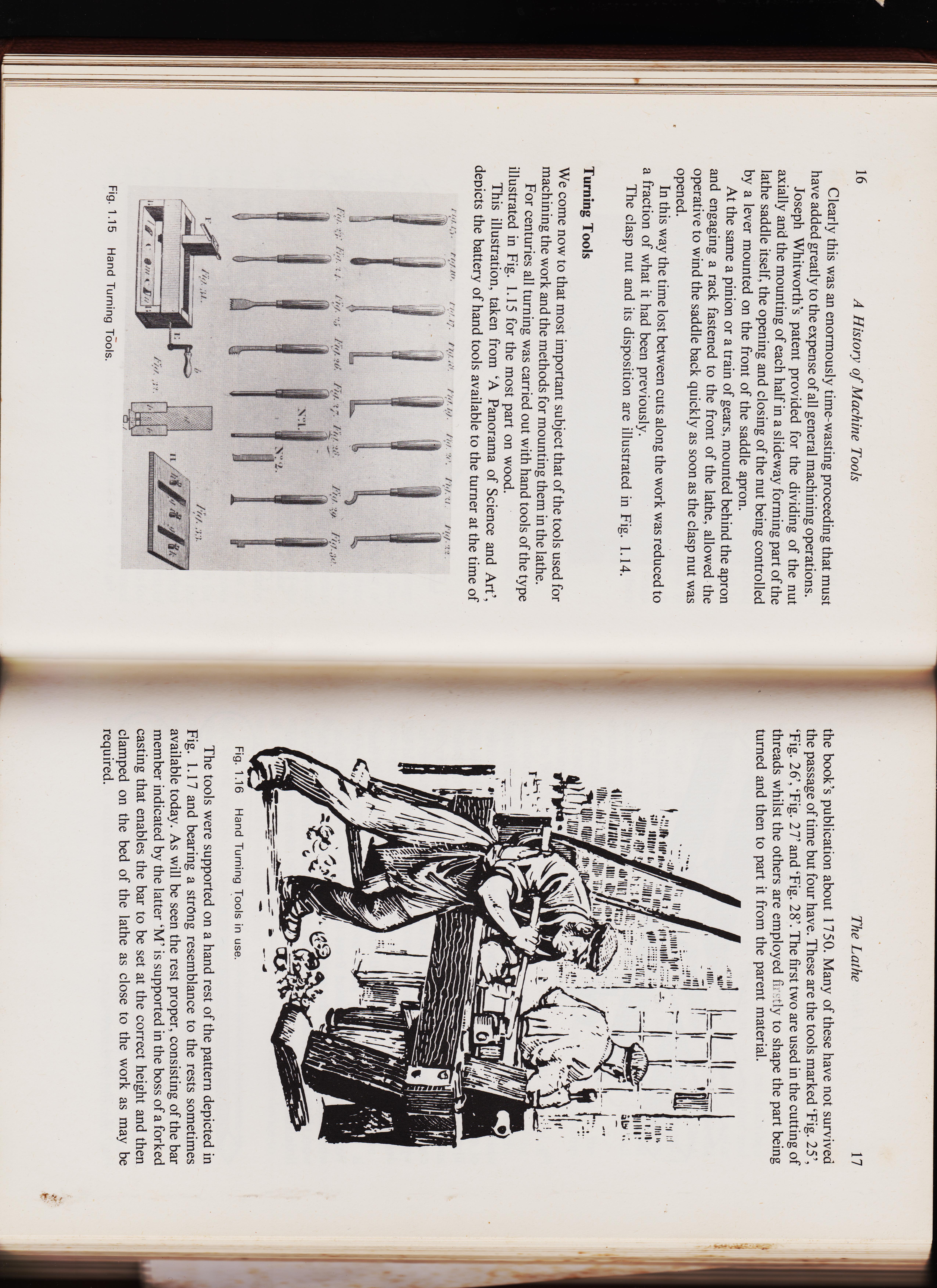
Turning Tools We come now to that most important subject that of the tools used for machining the work and the methods for mounting them in the lathe. For centuries all turning was carried out with hand tools of the type illustrated in Fig. 1.15 for the most part on wood. This illustration, taken from 'A Panorama of Science and Art', depicts the battery of hand tools available to the turner at the time of Fig. 1.15 Hand Turning Tools. The Lathe >
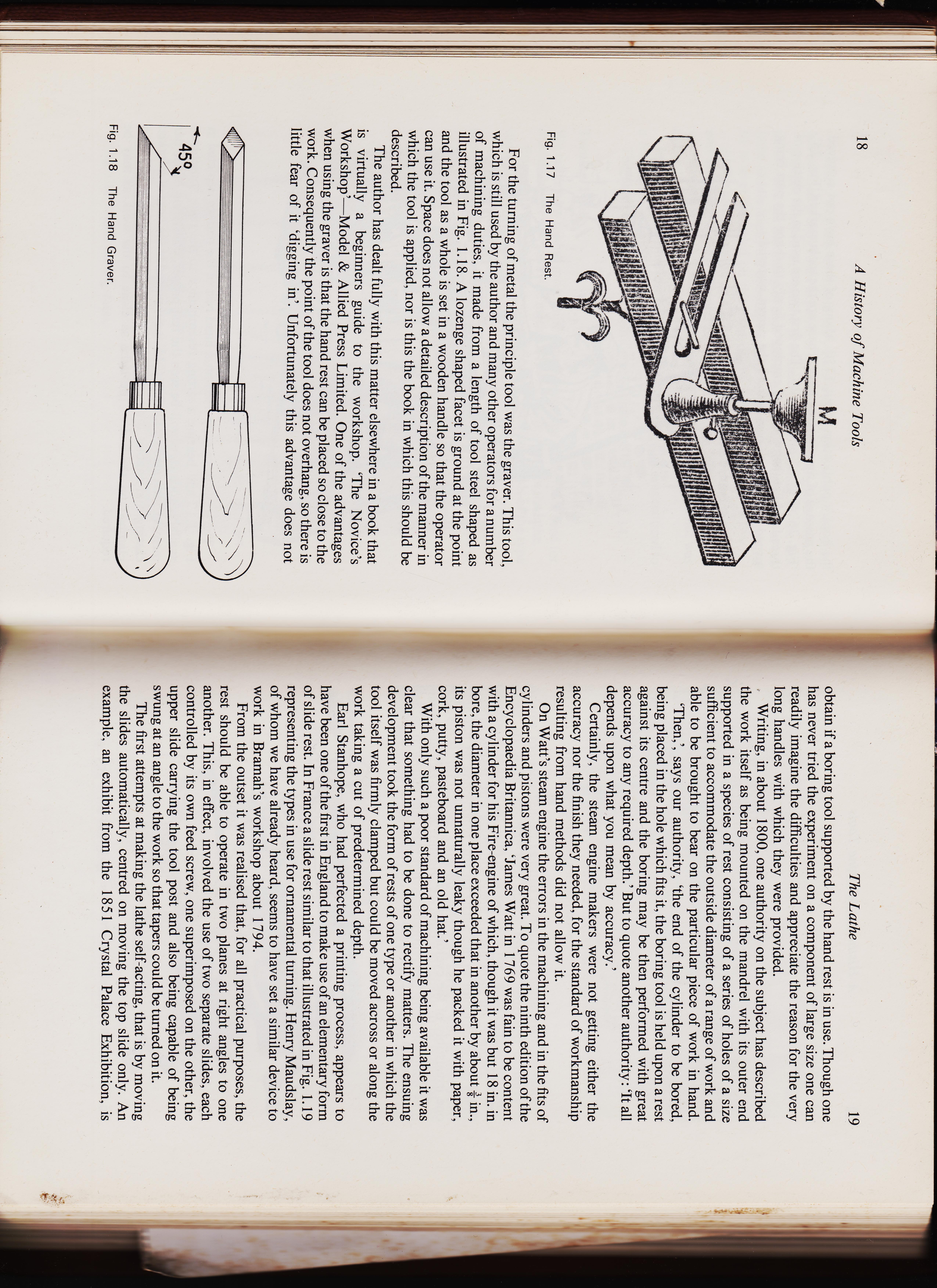
17 the book's publication about 1750. Many of these have not survived the passage of time but four have. These are the tools marked 'Fig. 25', `Fig. 26', 'Fig. 27' and 'Fig. 28'. The first two are used in the cutting of threads whilst the others are employed fi, tly to shape the part being turned and then to part it from the parent material. ig. 1.14 Fig. 1.16 Hand Turning Tools in use. The tools were supported on a hand rest of the pattern depicted in Fig. 1.17 and bearing a strong resemblance to the rests sometimes available today. As will be seen the rest proper, consisting of the bar member indicated by the latter 'M' is supported in the boss of a forked casting that enables the bar to be set at the correct height and then clamped on the bed of the lathe as close to the work as may be required.


<
AMERICAN-MACHINIST- page 16
pg 16
526-16 Charging A Cupola Furnace cont.
above it. 2d. In charging the cupola in a careless manner,
by throwing in pieces of scrap iron with many angles, so that they will lock in the sides of the brick and cause the furnace to hang, and the coke burns out from under them. 3d. Overcharging; that is, putting in more iron to a charge than the fuel is able to melt.
4th (This is oftener the cause than all the others combined). An insufficiency of fuel on the bed;
and this, I claim, is the most important thing connected with the working of the cupola, and particularly so in the melting of chilled iron. I have seen, time and again, in various places where I have worked, in big shops and in small, that after tapping out about the first charge, the cupola would refuse to melt and the bottom would have to be dropped; or, if it kept on melting, it would be where there was an excess of fuel be-tween the charges, and the iron would melt so slow and dull that the work would generally be spoiled, and the men, after standing around from half-an-hour to an hour, would be sent home and some of them laid off for want of floor room until the heat was finally taken off. When a cupola acts in this manner, it is plainly a case of insufficiency of fuel in the bed and too much between the charges. Now, there is a rule for the charging of fuel in the cupola which has never failed me since I found it out. It is a long way from the theoretical amount of fuel it should take to melt iron, but in practice it is correct. This refers strictly to cu-polas in which coke is used entirely; hav-ing been in the West for the past twenty-five years, I have not had much experi-ence with anthracite coal, not having used much for that length of time. Take, for example, a cupola 3o inches inside diameter, of brick, with 15 inches from iron bottom of cupola to bottom of tuyeres. This cupola will take a bed of coke of 571 pounds, with charges of iron of 1,250 pounds. This is as much iron as ought to be charged for safety if the iron is pig and heavy scrap; but if the scrap iron is light and compact, the charge may be safely increased to 1,50o pounds. The remaining charges of coke should be 75 pounds to 1,250 pounds of iron, or 162/3 to I. If it should be light, compact scrap, this can also be increased to 1,500 pounds charges. This will bring your iron down hot and fast, provided, of course, that the coke be Connelsville or its equal, and the cupola has been charged intelligently. Taking a 3o-inch cupola and 571 pounds charges of coke with 1,250 pounds charges of iron as units, then to charge a 42-inch cupola, 3o : 42 : 571 : W, the answer wanted ; or, 571 X 42 30 = 799, or 800 pounds of coke for a 42-inch cupola bed. The charges of iron would read 125o X 42 3o : 42 : : 1,250 : X ; or,30 = 1,75o pounds of iron would be. a safe charge for a 42-inch cupola. AMERICAN MACHINIST _ - As I mentione- -cove, if the scrap iron is small and compact, the charges in a 42-inch cupola can be increased to 2,000 per charge. Now, with regard to the coke charges after the bed, they would be 1,25o : 75 : : 1,75o : x; or, ,750 X 75= 105 1,250 pounds, the charge . of 'coke in a 42-inch cupola. This will melt the iron hot and fast, and with 1,750 charges any iron can be melted that is suitable for this size of cupola. This can all be done in a cupola with one range of tuyeres, and the ordinary air chamber around it, in using a Colliau cupola. This amount can be reduced a little, but not much, showing that perfect charging is the secret of cupola working. GRINDR OD. Helena, Mont. A A A Storing Pattern Lumber — Comput-ing Weight of Round Iron. Editor American Machinist: The matter of taking care of the lumber used in the pattern shop is generally more or less of a nuisance; and while the way I am about to explain is by no means per-fect, it has some good features, and I pre-sent it to the readers of the "American Machinist" after having tried it for more than a year and found nothing better. Our pattern shop is about 36 feet wide, with a half diamond truss of wood. As the roof is about one-third pitch, there is 116" IV Fig. 11A; Hole Fig. 3 ARRANGEMENT FOR HANDLING PAT-TERN LUMBER. quite a large space between the members of the truss, i. e., between the lower chord and the rafters. We decided to utilize this space for the storage of lumber. This was done by nailing vertical strips I x 2 inches onto the trusses, about 3 inches apart in the clear. Then a horizontal piece I x 3 inches was nailed to these, leaving a space so that boards 24 inches wide could be pushed on edge between the vertical strips. A similar arrangement was sus-pended between the trusses, so that short lengths of lumber could be stored. May 21, 1896. In Fig. I the lumber racks are on the right and left-hand sides, while a movable platform D occupies the space between and travels on the track C C, made of VA x 7-inch yellow pine. These rails C C are spiked to hangers, which are in turn spiked to timbers B B. The members A. A are the rafters of the trusses. When I proposed this arrangement, some objection was made on account of the cost; but, after all, the expense was very small and the device is simple. The platform is simply a frame shown in plan in Fig. 2, the sides and ends of which are x 7-inch yellow pine, braced as shown in Fig. 2, with strips II/2 x 3 inches. The wheels are about VA-inch face and about 7-inch diameter, and the axles are simply round rough rods of bar iron. The wheels were chucked and a flat drill rammed through them, and set screws hold them on the axles. The journal bearings are cast iron, made as shown in Fig. 3. I made the pattern for this job, and it took me probably a half-hour. The hole was drilled so the rough shafts would go through easy, and the bolt holes made themselves. Six of these castings were required, and were secured in place by 5/8-inch rods going clear through, thus tying the frame work to-gether. The decking is 1-inch rough boards. We can easily put io,000 feet of lumber up there, and it is not much of a job to get it there. Lumber seasons well there, and every individual board can be exam-ined readily, and, also, only as much as is wanted at a time need be cut off. A per-son can tell just what lumber is on hand and how much. It is true that the boards warp some, but they usually come back, and I have found no more difficulty on that score than when piled flat with hori-zontal strips between. We have had quite a shower of con-stants, formulae, etc., lately, and I will offer the following rule for estimating the weight of round bar iron. Of course, it is only approximate. I have never seen it. or heard of it, but it just occurred to me when running over a table of weights. This is the rule: Take the diameter in sixteenths and square it; point off two places: For instance—What is the weight per foot of a 3-inch round iron bar? 3 inches equal 48 sixteenths, 48 squared equals 2,304; pointing off two places gives the weight 23.04 pounds. The actual weight is 24.03. Take 2-inch shaft: 32 squared equals 1,024; pointing off two places gives 10.24 pounds. Actual weight, io.68 pounds. This is easy to remember and is close enough for many purposes. A. L. BOWEN. Fastening Piston Rods. Editor American Machinist: It is no wonder that Mr. Bullock did not give us his method of securing piston